

DC current digital transducer
This product is a 1-phase DC current acquisition and measurement digital isolation transducer. It can measure the current of the DC circuit. Using high-precision 24-bit dedicated AD chip, the ratio dynamic range can be up to 1000: 1. Using principle of Hall measurement or resistance sampling measurement, which is with high accuracy, good stability and high communication speed, the completely isolated processing technology is with anti-interference ability. Measurement of electrical parameters through the RS-485 digital interface output to achieve long-distance transmission, the product MODBUS protocol is complete compatible with a variety of configuration software or PLC equipment MODBUS (RTU) protocol. It can be applied to power, room monitoring, industrial measurement and other fields.
NO, | Item | Date | Unite | Remarks |
1 | Accuracy | 0.2, 1.0 | % | Terminal input 0.2, perforation input 1.0 |
Input range | MS3 case :5A; ES5 case :1000A; | The maximum range for each specification | ||
2 | Baud rate | 115.2K, 57.6K, 38.4K, 19.2K, 9600(default) 4800, 2400, 1200 | bps | Factory default communication format: 9600, N / 8/1, address 1; S5 type up to 19.2K; |
Communication | RS-485(twisted pair line) , RS-232C(treble line, only for N style parts) | RS422 optional | ||
Parity | None, Even, Odd, Space | |||
Max. number of nodes | 64 | Node | Only for RS-485 | |
Bus protection | 400W transient voltage | ESD protection and thermosnap | ||
3 | A/D SPEED | 100 | mS | |
4 | Working temperature | -20℃~+60℃ | ||
5 | Isolation voltage | Input/output: 2500V DC for 1 min Input/power supply: 2500V for 1 min Output/power supply: 2500V for 1 min |
V
| The double isolation part numbers, their output and power supply are grounded together, there is only between the input and output isolation voltage |
6 | Overload | 2 x voltage span 1 sec. 10 for times with interval of 10 sec. 10 x current span for 1 sec. 5 times with an interval of 300 sec (only for hole thru. parts) | The input outside the linear range will result in poor accuracy | |
7 | MTBF | >30000 | Hour | |
8 | Auxiliary power supply | +5V/+12V/+24V/+48V/ AC220V | V | 220VAC,DC only for N case parts |
9 | Power consumption | ≤250mW(+12V),≤500mW(+24V) | mW | Power consumption depends on power supply to be used |
10 | Temperature drift | ≤300 | ppm/℃ | (-20℃~+60℃) |


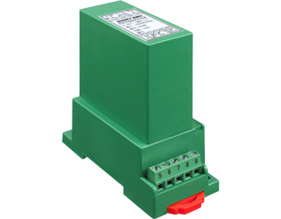
CE-AZ11-**MS3 Case

CE-AZ11-**MS3 Installation Diagram

CE-AZ11-**ES5 Case Type

CE-AZ11-**ES5 Installation Diagram

The wiring diagram of single-phase current CE-AZ11-**MS3
(Terminal NO.7 output is +5 V to provide 5V output (<20mA) in common ground with power supply)

The wiring diagram of CE-AZ11-**ES5
² Available with wide power supply: DC: 10-30V or 10-55V or AC/DC: 85-265V.
² With odd parity, even parity, no parity, 2 stop bits and other communication methods are free to set.
² Communication speed optional, the maximum communication speed to 115200 bps.
² The intelligent transducer with the smallest size and wide current measurement range in the peer.
² Electroplating has a positive and negative cumulative function, and power-down storage function.
² With red and green light-emitting diode instructions function, the red light indicates the normal operation of the product (100mS flashing), the green light indicates the product communication.
² High anti-interference ability, the input, output and power port to resist the surge voltage up to 2KV or more.