

Single phase AC current digital transducer
HOME > Current > One phase AC transducer with digital interface
This product is a single-channel AC current acquisition and measurement digital isolation transducer. It can measure the current of the AC circuit. Using high-precision 24-bit dedicated AD chip, the ratio dynamic range can be up to 1000: 1. True RMS measurement of current is with high accuracy, good stability and high communication speed, the completely isolated processing technology is with anti-interference ability. Measurement of electrical parameters through the RS-485 digital interface output to achieve long-distance transmission, the product MODBUS protocol is complete compatible with a variety of configuration software or PLC equipment MODBUS (RTU) protocol. It can be applied to power, room monitoring, industrial measurement and other fields.
NO, | Item | Date | Unite | Remarks |
1 | Accuracy | 0.2 | % | |
Input range | S3 case: 30A; ES5 case:700A DS5 case: 200A; N1 case: 5A; | The maximum range for each specification | ||
Frequency | Frequency response: 20Hz-1KHz; Frequency measurement: 20-600Hz | |||
2 | Baud rate | 115.2K, 57.6K, 38.4K, 19.2K, 9600(default) 4800, 2400, 1200 | bps | Factory default communication format: 9600, N / 8/1, address 1; S5 type up to 19.2K; |
Communication | RS-485(twisted pair line) , RS-232C(treble line, only for N style parts) | RS422 optional | ||
Parity | None, Even, Odd, Space | |||
Max. number of nodes | 64 | Node | Only for RS-485 | |
Bus protection | 400W transient voltage | ESD protection and thermosnap | ||
3 | A/D SPEED | 100 | mS | |
4 | Working temperature | -20℃~+60℃ | ||
5 | Isolation voltage | Input/output: 2500V DC for 1 min Input/power supply: 2500V for 1 min Output/power supply: 2500V for 1 min |
V
| The double isolation part numbers, their output and power supply are grounded together, there is only between the input and output isolation voltage |
6 | Overload | 2 x voltage span 1 sec. 10 for times with interval of 10 sec. 10 x current span for 1 sec. 5 times with an interval of 300 sec (only for hole thru. parts) | The input outside the linear range will result in poor accuracy | |
7 | MTBF | >30000 | Hour | |
8 | Auxiliary power supply | +5V/+12V/+24V/+48V/ AC220V | V | 220VAC,DC only for N case parts |
9 | Power consumption | ≤250mW(+12V),≤500mW(+24V) | mW | Power consumption depends on power supply to be used |
10 | Temperature drift | ≤300 | ppm/℃ | (-20℃~+60℃) |

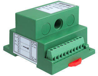
Case Style (marked in the figure Unit: mm)

Figure 5.1 CE-AI12-**BS3 product outline

Figure 5.2 installation diagram of CE-AI12-**BS3

Figure 5.3 CE-AI12-**MN1 product outline (220VAC power supply)

Figure 5.4 installation diagram of CE-AI12-**MN1

Figure 5.5 CE-AI12-**DS5 product outline

Figure 5.6 installation diagram of CE-AI12-**DS5

Figure 5.7 CE-AI12-**ES5 product outline

Figure 5.8 installation diagram of CE-AI12-**ES5
Terminal definition and connection diagrams
S3 case 1-phase current connection diagram figure 6.1(Current punch input, Φ6.5mm, max. 30A)

Figure 6.1 wiring diagram of CE-AI1 - ** BS3 (current input for terminal No. 1and 4)
(Terminal 7 output is +5 V to provide 5V output (<20mA) in common ground with power supply)
N case single phase current wiring diagram is shown in Figure 6.2; (current terminal input, the maximum 5A)

Figure 6.2 wiring drawing of CE-AI12 - ** MN1
Refer to Figure 6.3 for the single-phase current wiring diagram of S5 (current input, Φ11mm, max. 200A; Φ20mm, max.

Figure 6.3 wiring diagram of CE-AI12 - ***S5
Available with wide power supply: DC: 10-30V or 10-55V
With odd parity, even parity, no parity, 2 stop bits and other communication methods are free to set.
Communication speed optional, the maximum communication speed to 115200 bps.
The intelligent transducer with the smallest size and wide current measurement range in the peer.
Electroplating has a positive and negative cumulative function, and power-down storage function.
With red and green light-emitting diode instructions function, the red light indicates the normal operation of the product (100mS flashing), the green light indicates the product communication.
High anti-interference ability, the input, output and power port to resist the surge voltage up to 2KV or more.